
Introduction
One of the most basic applications of relays is to allow a low voltage signal to control a high voltage load. In this example, a discrete output of the Vesta controller is used to control a 120VAC circulator. We use the RC-4DD (formerly RM-1207) Relay Module which is controlled by the Vesta controller and can switch loads up to 220VAC.
This example shows a circulator, but the same process applies to any high voltage load that needs to be turned on and off by the Vesta, such as fans, lights, valves, or other electrical devices.
Required Items
- Configured and installed Vesta controller
- RC-4DD Relay module
- Code-compliant electrical cable (14-2 w/ground armored cable in this example)
- Cat5 (Ethernet) cable to connect Vesta and RC-4DD (Blue color preferred)
- Network-connected computer
Schematic
In this example, power for the circulator comes from standard 120VAC line voltage. One motor connection from the circulator is connected directly to the 'neutral' wire. The other lead is connected to a normally open contact in the RC-4DD. Finally, the common contact from the same relay contact set is connected to the 'line' wire.
When the Vesta controller energizes the relay, the circuit is completed and power is applied to the circulator.
NOTE: This is only a concept drawing. All wiring must be performed in accordance with applicable codes. Final design is the responsibility of the system designer or installer.
Physical Wiring
Physical wiring follows the schematic above. In this case, we're using relay 1, which is at the bottom right. We're only using one of the two contact sets, and we're connecting to the common (C) and Normally Open (NO) contacts.
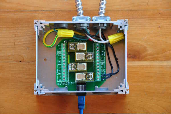
120VAC line in is the cable at top center, and the cable at top right goes to the circulator. The blue Cat5 cable goes to a discrete output connector on the Vesta. In this example we're using the connector labeled ''5-8'.
At this point, physical setup is complete. The next section deals with setting up the Vesta to control the circulator.