
This is a more sophisticated application of relays. In this case, we have a variable speed blower on a boiler that was originally managed by a controller on the boiler. Since the boiler control logic somewhat simplistic and can't be modified, we want to see if we can develop rules that provide more effective control of blower speed using the Vesta system. However, we want to be able to return to the original configuration in case our experimental rules are not providing the desired results. In fact, we'd like the boiler to work the same way as it originally did if we simply turn off or disconnect the Vesta controller. This is known as fail-safe operation. If the Vesta controller is taken out of the picture, the system works exactly as it did before.
There are two wires going to the blower. We'll use a single relay in the RC-4DD (Formerly RM-1207) relay module to switch these wires between the original boiler controller and the Vesta's VS-1108 variable speed control module.
Each relay coil in the RC-4DD is connected to a discrete output channel in the Vesta controller. This allows the Vesta to activate any relay based on rules that you define, or through the Graphical User Interface.
Here's a schematic of what we need to do. This example shows a single relay in the RC-4DD.
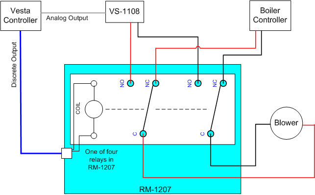
In this example, the wires from the blower are connected to the relay's common contacts. The blower control outputs from the boiler are connected to the normally closed contacts. This way, the blower is connected to the boiler controller any time the relay is not activated.
The blower control outputs from the VS-1108 are connected to the relay's normally open contacts. When the relay is energized, the blower will be connected to the VS-1108 and the Vesta will be able to control its speed.
During development, the relay might be controlled by a clickable button on the Graphical User Interface so that the user can switch instantly between Vesta control and Boiler control of the blower. Once the Vesta rules are satisfactory, an 'always true' rule can keep the relay permanently in the energized position.
Note: This is only a partial solution to illustrate a possible use of relays. In order to protect the variable speed circuitry, there would need to be some logic or safeguards to prevent the blower being switched between controllers when either controller is 'on'. Suddenly switching the load while under power can cause damage.
Note: In some cases the only intent might be to allow the Vesta to turn the blower off. In this case the wiring between the boiler, the relay, and the blower is the same. The VS-1108 is not required, and nothing would be connected to the relay normally open contacts. Wired this way, energizing the relay simply removes power to the blower, turning it off.