
Solution
The solution to this problem was to give the Vesta controller information about the demand from the greenhouse zones and let it control P15 to achieve the desired Glycol temperature.
The commercial zone controllers were removed along with the motor drive for the mixing valve. The mixing valve was set to straight-through (no mixing).
The following Vesta hardware was used:
- Vesta controller (already on-site and in use for other functions)
- RI-024A (formerly RM-1210) relay input box to sense demand from each zone
- VS-1108 controller to vary the speed of P15
- Two temperature sensors to measure Glycol and return water temperatures
The RI-024A relay box has four relays with 24VAC coils. Each relay has a contact that's sensed by the Vesta and an extra contact that can be used to control an external device. In this application, the spare contacts are used to control circulators P16, P17, and P18. Here’s a schematic showing the connections in the RI-024A relay box:
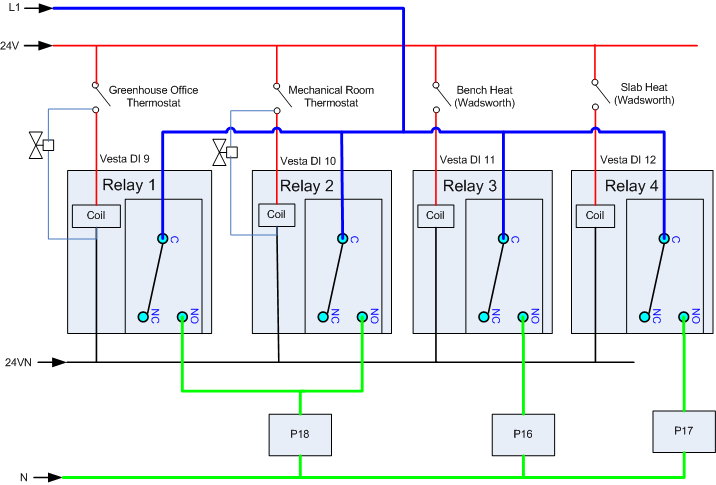
In each case, the thermostat (or dry contact) completes a low-voltage circuit that activates a relay. The Vesta can sense the relay closure. The relay contacts also provide power to the appropriate circulator. In the case of the office and mechanical room, the thermostat also provides power to a motorized zone valve. This wiring replaces the functions provided by the commercial zone controllers, while adding the ability for the Vesta to monitor and respond to zone demands.
The wiring in the relay box takes care of all devices except P15, which will be managed by the Vesta controller.