
Front Panel Example
The Vesta is delivered with a simple set of rules that use the user-assignable three position switch and LEDs on the controller front cover. This example does not require any external hardware to be connected. Turn on your controller and connect to it to follow the discussion in this section. This configuration and rule set is backed up as 'LedSample' on the Vesta. Some older Classics have a slightly different LED front panel example, but the concepts are the same.
Each rule type will be covered in detail in the following sections. This section is intended as a quick introduction to rules.
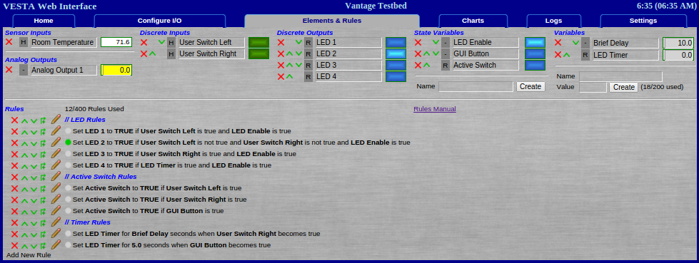
Figure 4.1: Front Panel Example
On the Vantage and Pro, this page is interactive. Data element values and rule status indicators are updated continuously. Discrete outputs and state variables can be toggled on/off by clicking on the blue rectangular status lights.
The top portion of the screen shows all of the data elements that are available on the system. Below that, the rules are listed in the order that they will be evaluated.
Comments are in blue and preceded by '//'. In this example, comments break the rules into three sections.
Rules can be rearranged. The icons next to each rule allow the following actions:
- Delete the rule
- Move the rule up
- Move the rule down
- Insert a new rule above the rule
- Edit the rule
There's also an indicator next to each rule that shows whether the rule is currently (on the Classic, as of the last refresh) 'active'. In the example above, only one rule is active.
Desired Behavior
For the purposes of this example, we'll make use of the following data elements:
| Name | Type | Description |
|---|---|---|
| LED 1 | Discrete Output | Front Panel LED |
| LED 2 | Discrete Output | Front Panel LED |
| LED 3 | Discrete Output | Front Panel LED |
| LED 4 | Discrete Output | Front Panel LED |
| User Switch Left | Discrete Input | True if user switch is in the left position |
| User Switch Right | Discrete Input | True if user switch is in the right position |
| LED Enable | State Variable | Not connected: Set via GUI |
| GUI Button | State Variable | Allows user to turn on LED from GUI |
| Active Switch | State Variable | Indicates that at least one switch is 'on' |
| Brief Delay | Variable | Holds delay value for LED timer |
| LED Timer | Variable | Used for illuminating LED 4 |
The desired behavior is as follows:
- Illuminate LEDs only when the LED Enable button is pressed
- If the user switch is in the 'left' position, illuminate LED 1
- If the user switch is in the middle position (neither left nor right) illuminate LED 2
- If the user switch is in the 'right' position, illuminate LED 3
- When the user switch is moved to the 'right' position, illuminate LED 4 for a period determined by the value of the 'Brief Delay' variable
- When the GUI Button is pressed, illuminate LED 4 for 5 seconds
- If the user switch is in either the right or left positions, or if 'GUI Button' is pressed, set 'Active Switch' to TRUE
These desired behaviors are of course completely arbitrary and have been developed for the purposes of illustration only. On the Vantage and Pro, the LED Enabled and GUI Button buttons can be clicked on and off on the Elements & Rules tab. For the Classic, the buttons can be clicked on and off via the GUI tab which is described here.
Rules for LED Control
The first three rules in the LED control section implement the first three desired behaviors:
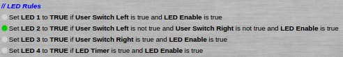
The rules are almost an exact restatement of the desired behaviors. Note that all rules are in the general form "Set (some element) to (some value) under (some condition)". Remember that TRUE and FALSE are predefined variables.
The fourth rule implements the fourth desired behavior based on a timer. The timer rules are in the third section and will be discussed there.
Rules for the 'Active Switch' state variable
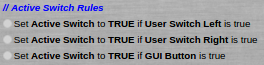
These three rules serve to set the 'Active Switch' state variable to true if the user switch is left or right, or if the GUI Button is true. Since it's a state variable, it will have a value of false if none of these rules set it to true.
Timer Rules
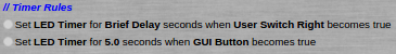
There are two timer rules:
- Any time the switch is moved to the 'right' position, set LED Timer for the number of seconds represented by the 'Brief Delay' variable - 10 seconds in this case
- Any time the GUI Button becomes true, set LED Timer for 5 seconds
Note that one rule uses a variable to determine the timer delay, while the other uses a plain numeric value. When LED Timer is set, it will immediately begin counting down. As long as it is non-zero, LED 4 will be turned on based on the fourth rule in the LED section above.
Front Panel Uses
Once you're done using the front panel to learn about programming, it still has a few uses:
- Testbed for new rules. Rather than testing a new set of rules on actual hardware, create the rules exactly as they will be except have them turn on LEDs rather than actual pumps and valves. If the rules aren't doing exactly what you want, no harm done.
- Substitute input for testing. If you have a rule that's triggered by something that's not well suited for testing - an over temperature switch, for instance - you can test the rule using the front panel switch as the input. Simply update the rule to use the actual input once you're satisfied.
- User input and / or status displays. In some cases there may be a need for user input or a desire to provide visual status indication. Simply label the switch and/or LEDs as needed and build rules. For example, you might use the LEDs to indicate important operating modes. You might use the front panel switch to allow the user to set a particular condition - Summer vs. Winter, or Manual / Automatic / Off.