
Sensors
Sensor Types
There are three commonly used sensor types for the Vesta controller - general-purpose TS-1058 temperature sensors, TS-1060 thermocouples, and TS-1061 thermistor sensors. There are many other types, but these cover most applications. They are electrically quite different, but the Vesta controller can accommodate any sensor type on any channel.
The TS-1058 sensors work over a range from about -20°F to 212°F. They are inexpensive and in the Vesta controller they provide a temperature resolution of better than a tenth of a degree Centigrade.
The TS-1060 sensors are standard type K thermocouples. They require an external amplifier (part number TCA-1125). They can measure temperatures from 32°F to about 2500°F.
As configured for the Vesta controller, the TS-1061 sensors cover the range from about 40°F to over 300°F (limited by melting of the cable insulation). Because thermistors are highly nonlinear, they provide much better resolution at lower temperatures. At room temperature their resolution is better than a tenth of a degree, but at boiling the resolution is only about a quarter of a degree Centigrade. They are smaller than the TS-1058 sensors and can fit in tight spaces.
Connecting Sensors
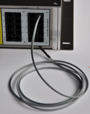
The Vesta can accommodate a total of 16 sensors. Sensors use telephone-style (RJ11) connectors. On the Vesta controller, sensor connections are grouped into four rows with four connectors on each row. Sensors may be plugged directly into these connectors.
There is also a fifth connector on each row. This is a standard Ethernet style (RJ45) connector that allows use of a sensor breakout box. A breakout box can be used if you have a group of sensors at a remote location - in a nearby building, or on the roof, for instance. Rather than running four long individual sensor cables to the remote location, you can run a single Ethernet-style cable to the remote location, and then use a sensor breakot box to connect the individual sensors. For each row of four sensors on the Vesta, either the individual connectors OR the breakout box may be used - not both.
Physical I/O Tab
Sensors are configured using the 'Physical I/O' tab on the Vesta controller web interface. This tab displays all of the possible inputs and outputs for the Vesta controller, and allows you to specify which inputs and outputs you will use in your application. Sensor inputs are identified as Analog Inputs on this page.
Because there are so many inputs and outputs, the Vesta controller allows you to specify which ones you're going to use. Only selected inputs and outputs are visible outside the 'Physical I/O' page. In the Vesta controller, the process of selecting a physical I/O involves three steps:
Identify connector number on the outside of the controller where your sensor or other device is plugged in. For instance, the sensor inputs are on top right side of the Vesta controller and labeled with channel numbers from 1 to 16 (by default - different models may have different numbers of inputs). The picture above shows a sensor plugged into channel 1.
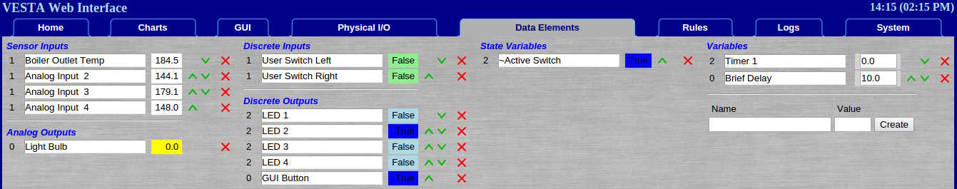
Find the corresponding line in the 'Physical I/O' page. In our example, the first line on the 'Physical I/O' page corresponds to Analog Input 1. To use a physical I/O in the Vesta controller, you must select it by clicking the 'Create Element' link in the rightmost column of the 'Physical I/O' page. In this example, an element has already been created and assigned the name 'Analog Input 1'.
For each sensor, make sure that the correct sensor type is selected. The most commonly used sensor in the Vesta controller is the TS-1058.
Finally, go to the 'Data Elements' tab and give your sensor a meaningful name. Here, we'll choose 'Boiler Outlet Temp':
As each sensor is added, check to see that a reasonable temperature is displayed. Holding the sensor between your fingers should result in a quick rise in displayed temperature.
Calibration
The Vesta controller allows calibration of both gain and offset for each sensor. In most cases, calibration is not necessary. If calibration is desired, an offset calibration is usually all that's needed. Offsets are simply added to the measured temperature.
To get the highest possible accuracy, gain calibration can be done as well. To perform gain calibration, you need to establish two known temperatures that are as far apart as possible while remaining within the sensor's measurement range. The easiest way to do this is to use an ice bath and boiling water. Immerse the sensors in an agitated (stirred) bath of water packed with crushed ice. This will be very close to 0°C (32°F). Water at a vigorous boil will be very close to 100°C (212°F). If you're at a high altitude, you'll have to correct for altitude effects.
Use the sensor calibration page to calculate gain and offset. Follow the instructions in the spreadsheet - enter the actual low and high temperatures (use a reference thermometer if you have one, otherwise use freezing and boiling). Enter the readings for each sensor at low and high temperatures. The blue cells in the spreadsheet will then give you the values for gain and offset for each sensor. Enter those values in the Physical I/O tab.