Vermont Energy Control Systems

Practical monitoring and control for the real world

User Manual - Vesta Vantage or Pro | Vermont Energy Control Systems

Vermont Energy Control Systems

Practical monitoring and control for the real world

Introduction

This document covers initial setup, configuration, and use of the Vantage and Pro controllers. Much of the content in this manual is the same as the Vesta Classic user manual, but the Vantage and Pro have additional capabilities as well as some differences in the user interface. In addition to this document, there are two companion documents:

  1. Rule Programming - creating rules to control external devices
  2. Graphical User Interface - creating custom 'live' graphical user interfaces

For your convenience, there is a table of contents at the top of each page in this manual as well as the option to view the entire manual as a single page (the 'All Pages' link at the end of the table of contents). The topics covered are as follows:

  • Terminology- concepts, specialized terms, and conventions used in this and other documents
  • Initial Setup - turning on and connecting to your Vesta for the first time
  • Web Interface - a brief description of the Vesta web interface
  • Front Panel - purpose and use of the front panel LEDs and switch. Overview of the preinstalled sample application
  • Inputs and Outputs
    • Sensors - connecting, configuring, and calibrating analog sensors
    • Discrete Inputs - connecting and configuring discrete inputs
    • Relays - general discussion of relays and their use with the Vesta
    • Discrete Outputs - connecting and configuring discrete outputs
    • Network I/O - getting data from remote Vesta systems
    • Forecast Data- using the forecast feature to obtain NOAA forecast data
    • Insteon Devices - connecting, configuring, and using Insteon home automation devices
    • Wireless Sensors - connecting, configuring, and wireless sensors
    • 1-Wire Devices - connecting, configuring, and using 1-wire devices
    • Analog Output - using analog outputs to provide variable speed control

Disclaimer: This documentation is under construction. Every effort is being made to ensure that it is accurate and complete. However, it is entirely possible that it may contain errors and omissions. If you see a problem, please contact Vermont Energy Control Systems.

User Manual - Vesta Vantage or Pro | Vermont Energy Control Systems

Vermont Energy Control Systems

Practical monitoring and control for the real world

Terminology

Every discipline has its own terminology. Electrical engineers, programmers, electricians, and controls engineers all use specialized vocabulary, often with different words to describe the same thing. This section describes the concepts and terms used in Vesta documentation.

I/O: Input and Output - data or values coming into the Vesta from the outside world, or being send from the Vesta to the outside world.
Variable: A user-defined internal 'scratchpad' used by the Vesta to hold a value for future use. For instance, you might define a variable called 'Main Floor Setpoint' that would hold the value of the desired main floor temperature.
Discrete: An input, output, or variable which can be in one of only two states, generally corresponding to 'on or 'off'. Sometimes referred to as 'Binary', 'Digital', or 'Boolean'. See table below for examples.
Analog: An input, output, or variable which can have a wide range values. Analog inputs are typically used to measure values such as temperature or humidity.
State Variable: A discrete variable - a variable that can only have two states.
Data Element: In the Vesta, 'Data Element' means any input, output, or variable - any data that's available to be displayed, logged, or used in rules.

Discrete Values

The Vesta controller is at its core a computer, and it processes rules as a computer does. In the physical world, a pump may be on or a contact may be closed or a coil may be energized. Inside a computer, these states are represented as TRUE or FALSE values. The Vesta controller uses TRUE and FALSE in the following ways:

TRUE means 'on' or 'non-zero' or 'active'. The implication is that something is happening.

  • For contacts, TRUE means 'closed'.
  • When a discrete output is TRUE, power is being supplied to the relay coil, LED, or whatever the discrete output is driving.
  • For a timer or any numeric value, TRUE means non-zero.

FALSE means 'off' or 'zero' or 'inactive'.

  • For contacts, FALSE means 'open' - no current is flowing.
  • When a discrete output is FALSE, no power is being supplied.
  • For timers and numeric values, FALSE means zero.

TRUE and FALSE are not typically used with temperatures or other values that can have a fractional part, because the results can be unexpected. A temperature of 0.001 degrees will display as '0', but is actually non-zero and will be treated as TRUE.

Here are different words that can be used to describe each of the two states that a discrete may have.

TRUE FALSE
On Off
Active Inactive
Non-Zero Zero
Bright Dark
Closed Open

Electrical Connection and Signal Types

The Vesta controller is designed to connect electrically to a variety of physical devices. Electrical connections are divided into four broad categories:

  1. Power. Electrical power to run or operate a device.
  2. Communication. Ethernet, USB, or other connections used to transmit data between intelligent devices.
  3. Analog. Electrical signals that can have a range of values. The output of a typical temperature sensor would be an example.
  4. Discrete. Electrical signals that can have only two values such as off/on, open/closed, or active/inactive. Also called digital signals.

The Vesta controller uses all four categories. Power is straightforward, and communication is usually only the Ethernet connection. The bulk of the connections (and complexity) are the analog and discrete signals. The Vesta controller supports both inputs and outputs for these types of signals. They're typically used as follows:

Analog Inputs are to read temperature and other types of sensors that can measure a range of values.

Analog Outputs provide a signal that can be used to drive certain pumps, fans, or valves to variable speeds or positions.

Discrete Inputs are typically used to detect contact closure. Each discrete input consists of a pair of wires. If the input wires are shorted together, the input is sensed as 'TRUE'.

Discrete Outputs provide the ability to turn on or activate an external device such as a relay or an LED. A discrete output that's on provides 12 Volts.

All programming and control of the Vesta controller is accomplished through the use of these four electrical signal types.

Color Codes

For external connectors, colors are used where possible to help minimize the chances of plugging the wrong cable into the wrong connector. Each signal type has a unique color as follows:

  • Analog Inputs are grey (or white)
  • Analog Outputs are yellow
  • Discrete Inputs are green
  • Discrete Outputs are blue

These colors are also used in the web interface when displaying values for discrete inputs and outputs. While it's not required, using matching cables will help prevent mistakes.

Connectors

A picture of a CAT5 connector

The Vesta uses standard cables, connectors, and related tools that are readily available on this site and at most hardware stores.

RJ45: The Vesta controller uses standard RJ45 connectors for some of the I/O. These are 8 conductor connectors that are used for Ethernet cables. The male connector is easily crimped onto standard Ethernet cable with an inexpensive tool. The female connector is designed to snap into a panel (such as a wall plate) and is known as a 'keystone' connector. Electrical connection to the female connector is accomplished by pressing wires into slots in the back of the connector with another inexpensive device called a 'punchdown' tool.

RJ11 and RJ12: These are the connectors that are often used for telephone cables. They have positions for six conductors, but often only four are used. They look identical to RJ45 connectors, except that they are narrower. A connector that uses all six conductors is called RJ12, while a connector that only uses the middle four conductors is called RJ11.

User Manual - Vesta Vantage or Pro | Vermont Energy Control Systems

Vermont Energy Control Systems

Practical monitoring and control for the real world

Initial Setup

This section deals with physical setup and initial power-on check.

It's usually a good idea to connect your new Vesta and make sure that everything is working and configured properly before installing it in its permanent location. This video is a quick (5 minute) overview of initial setup. It shows the Classic, but the process is the same for all models. The user interface differs slightly: refer to the web interface section of this manual.

There a few requirements for Vesta installation:

  1. A dry and relatively clean location
  2. A 110Vac wall outlet to plug the power supply into
  3. A network connection
  4. The configuration sheet that came with your Vesta

Network Connection

Internet access is not required, although it's desirable. At a minimum, a network connection of some sort is necessary for initial configuration the Vesta controller. Once it's set up, network access is not necessary.

If your Vesta has the Wi-Fi option, you'll still need a physical Ethernet cable during initial setup to configure the Wi-Fi.

Location

The Vesta controller must be installed in a dry location that does not experience condensation and where temperatures do not exceed 140 degrees Fahrenheit. Since it has no fan and is in an enclosure, dust is not a serious problem, although electrically conductive or corrosive dust should be avoided. It does not need to be physically near the equipment that is to be controlled, although it is desirable to choose a location that minimizes the length and installation effort of the cables between the Vesta controller and the equipment that is to be monitored and controlled.

No tools are required. However, it's very helpful to label sensor cables and other wires as they're connected. A labelmaker or wire labels are strongly suggested.

Physical Setup

A picture of the Vesta's side panel

Figure 3.1: Side Panel with Power and Ethernet Connectors

Unpack the controller and place it in a convenient clean and dry location. It may be mounted on any horizontal or vertical surface that's protected from water. Initially, only network and power connections are needed. Plug an Ethernet cable into the white connector on the left side. Make sure that the power switch is in the 'Off' (down) position, and connect the wall-mounted power supply. The connector is next to the Ethernet port.

Turn on the power. If the Vesta controller is in its standard as-delivered configuration one of the LEDs on the front panel should illuminate after about 30 seconds.

Note: If your Vesta is part of a kit or if you ordered custom configuration, the front panel LEDs may not be present or may not illuminate.

Initial Connection

In the default configuration, the Vesta will automatically configure networking as needed for the network you connect it to. Once it has booted, you should be able to connect to it using the 'Internal Web URL' link on the configuration sheet that came with your unit. Start up a computer and open a web browser (Chrome, Firefox, Safari, Internet Explorer, or your favorite alternative). Get the configuration sheet that came with your Vesta and type the 'Internal Web URL' into your browser's URL bar. The URL will be in the form 'http://www.vecs.org/t.php?serial=xxxxxxxx'

After a brief delay, you should see your Vesta web interface:

A screenshot of the Vesta home page with the URL 192.168.1.179 visible

Figure 3.2: Home Page with URL

In this example, the IP address is 192.168.1.179 and the display shows configuration details that may differ from unit to unit. If this does not work, refer to the document on network troubleshooting.

At this point, plugging a temperature sensor into the first Sensor Input connector (right side, white connector group) should result in a display of the sensor's temperature.

Create Browser Bookmark

The IP address may change, so it's very helpful to create a bookmark using the URL from your configuration sheet. The mechanics of doing this vary depending on the browser that you use, but all of them support this process. Copy the URL text from the configuration sheet and create a bookmark with that text in your browser:

A screenshot of the user copying thr web address of the Vesta homepage

Figure 3.3: Copying Internal Web URL

The URL will be in the form 'http://www.vecs.org/t.php?serial=xxxxxxxx&access=internal', where 'xxxxxxxx' is your unit serial number. If you intend to access your Vesta from external locations (such as via SmartPhone or from work) bookmark the external web URL as well.

User Manual - Vesta Vantage or Pro | Vermont Energy Control Systems

Vermont Energy Control Systems

Practical monitoring and control for the real world

Web Interface

In almost all cases, configuration and interaction with the Vesta controller is through a web interface. The Vesta controller has a built-in web server which provides access to the system.

A screenshot of the web interface showing the home tab

Figure 4.1: Web Interface Showing Home Tab

This web interface has six tabs:

  1. Home: A passive display (you can't change anything) that shows current values and system status. No password is required.
  2. Configure I/O: This is where you configure the Vesta's sensors and other inputs and outputs.
  3. Elements & Rules: Primary system interaction tab. Create, rename, and edit rules and variables. Set values and monitor behavior.
  4. Charts: Interactive charts for reviewing logged data.
  5. Logs: Download system logfiles and logged data for any day.
  6. Settings: System settings, software update, backup & restore.

Each tab will be described in this manual.

User Manual - Vesta Vantage or Pro | Vermont Energy Control Systems

Vermont Energy Control Systems

Practical monitoring and control for the real world

Home Tab

The home page displays current values for all configured inputs and outputs. It also displays the system rules and the status of the system software processes. The home page does not require a password, since it provides only a passive view of system data. On your local network, it will automatically update values and rule status.

Screenshot of Vesta Home Tab

Figure 5.1: Home Tab

Top Section

The top portion of this page shows the current value for each input, output, and variable in the system, collectively referred to as 'data elements' in this document.

There's a letter next each data element that identifies the system task that's responsible for providing the values that you see. These letters match the first letter of the task names in the status section below. For example, task R is the rule engine and H is the Hardware I/O task. Any data element with a '-' next to it gets its value from the user - there's no system task that will provide a value.

This is covered in more detail in the programming guide.

There's a colored border around each data element value. This color indicates the status of that value:

  • Green: The value is valid and up to date as far as the controller can determine.
  • Yellow: The value has not been updated as recently as expected, but is not seriously out of date.
  • Red: The value is suspect - out of range or out of date.
  • Black: The controller cannot tell whether the value is valid or not. This can happen with sensors that report only when an event happens, such as Insteon door sensors.

System Status

This section shows status of all the software processes that are supposed to be running on the system. Green is good, yellow indicates a (potentially) temporary problem, and red indicates a failure. Selection of the processes that are intended to be running is accomplished on the 'Settings' tab.

Rules

This section lists all the rules that have been defined. Any active rule will have a green dot next to it. This can help quickly show what's happening with the system. In this example, the rule setting LED 3 is active. LED 3 is 'TRUE' (on) because 'User Switch Right' is true and 'LED Enable' is true.

To aid in understanding what's going on in a more complex configuration, hovering the mouse over the name of any data element will highlight all the places where that data element is defined or used. In this case, we can see that 'User Switch Right' is defined as a discrete input (that's currently TRUE - see the indicator next to it in the top section). 'User Switch Right' is also used in three rules.

User Manual - Vesta Vantage or Pro | Vermont Energy Control Systems

Vermont Energy Control Systems

Practical monitoring and control for the real world

Configure I/O Tab

The Vesta has a large number of channels of physical I/O, and only a fraction will be used in any single installation. To keep from cluttering every page with unused channels, the Vesta only displays channels that are actually in use. This tab is where you identify which channels you wish to use.

For sensor inputs and analog outputs, there are a wide range of devices that might be plugged in. The details of setting up specific I/O types are covered later, but in all cases the first step is to identify a channel that you want to use.

There are multiple sub-tabs on this page - one for each category of I/O. The example below shows the Analog Inputs sub-tab, but all the others provide similar functionality.

A screenshot of the Configure I/O Tab showing Analog Inputs

Figure 6.1: Configure I/O Tab showing Analog Inputs

Analog Inputs

This sub-tab is used select the appropriate sensor type for each sensor that's plugged into the Vesta 'Sensor Input' connectors. The analog sensors section of this manual covers this in more detail.

Analog Outputs

This sub-tab is used select the appropriate output scaling for devices being controlled via analog outputs. The analog outputs section of this manual has additional detail.

Discrete Inputs and Outputs

Discrete inputs and outputs are very similar. Use of this sub-tab is covered in the Discrete I/O section.

Network Inputs

This sub-tab allows configuration of networked inputs. This allows you to get data from another Vesta and treat it as if it were an additional channel. Use of this sub-tab is covered in the Network I/O section. Network inputs can also be used to get NOAA forecast data. This is covered on the Forecast Data page.

Insteon I/O

This section is only relevant if you have the Insteon option. In this section you can add and remove Insteon devices and decide which Insteon device data you wish to make available to the Vesta system.

Details on Insteon device configuration are covered in the Insteon section.

Wireless I/O

This sub-tab allows configuration of wireless sensors and other wireless devices. Use of this sub-tab is covered in the Wireless Sensors section.

1-Wire I/O

This sub-tab allows configuration of 1-Wire sensors and other 1-Wire devices. Use of this sub-tab is covered in the 1-Wire Devices section.

User Manual - Vesta Vantage or Pro | Vermont Energy Control Systems

Vermont Energy Control Systems

Practical monitoring and control for the real world

Elements & Rules Tab

This is the primary working tab for working with the Vesta, and is password protected. This tab is similar in layout and appearance to the 'Home' tab, and like the Home tab it provides continuous live update of element and rule status and values. However, this tab provides additional capabilities:

  • The ability to rename data elements
  • Creation and deletion of rules and variables
  • Reordering of data elements and rules
  • Setting values for variables and outputs
A screenshot of the Elements & Rules tab

Figure 7.1: Elements & Rules Tab

This screenshot shows the sample rule set that's configured on new Vesta systems by default. Even in this simple example, there's quite a bit going on. This is a complex page, and it's important to understand each section. We'll go through this page in detail, starting at the top.


Edit Mode, Custom GUI, and Resource Usage

A screenshot of Edit Mode, Custom GUI, and Resource Usage

Figure 7.2: Edit Mode, Custom GUI, and Resource Usage

  1. The user has chosen an edit mode of 'Delete Items'.
  2. There are a few 'Custom GUI' pages available.
  3. We've used relatively few of the available rules and data elements.

1: Edit Modes

In newer Vesta models (software version 3.1.1590 and newer) the Elements & Rules tab has multiple edit modes. These are primarily intended to reduce the chance of making accidental changes - especially deletions. There are four edit modes:

  • Change Values: The values of outputs and variables can be changed. Rules can be edited.
  • Move Items: Same as 'Change Values', but the order of elements and rules can be changed. New elements and rules can be created.
  • Delete Items: Same as above, except elements and rules can be deleted. Use with caution.
  • Simulate: This is a special mode for testing rules. To use this mode, first go to the 'Settings' tab turn off any hardware I/O processes. In 'Simulate' mode the user can set the values of sensors and discrete inputs.

2: Custom GUI Pages

The Vesta provides the ability to create custom Graphical User Interface (GUI) pages. The buttons in this part of the page provide access to any existing custom GUI pages. Custom GUI pages can be configured to be accessed without a password (Public) or password protected (Private). There's a separate manual here that covers the custom GUI feature in detail. In this example there's the blank 'default' GUI that's distributed with the Vesta as well as a two created by the user - a public GUI named 'test' and a private GUI named 'pqm2'.

3: Resource Usage

The Vesta has some limits on the number of data elements and rules allowed. These limits may vary by model and application, but this section of the the Elements & Rules tab shows both current usage and the Vesta's limits.


Data Elements: Values, Status, and Editing

A screenshot of Data Elements: Values, Status, and Editing

Figure 7.3: Data Elements: Values, Status, and Editing

This section of the page deals with Data Elements. In the image above, there are several things going on:

  1. There are two sensor inputs. The one named 'Outdoor Temp' has a red border around the value which tells us that it's currently invalid. In this case, the Vesta has detected that the sensor is not connected.
  2. There's an analog output named 'Circulator Speed' with a value of 0.0. The '-' to the left tells us that there isn't any process setting its value.
  3. The illuminated green rectangle next to the discrete input 'User Switch Right' tells us that the user-definable switch on the front cover is in the rightmost position.
  4. The illuminated blue rectangle next to discrete output 'LED 3' tells us that front panel LED 3 is on. Of course, if we're within sight of the Vesta, we probably know that anyway.
  5. No process is setting the values of the two state variables, so they can be set by the user - simply clicking on the blue rectangles will toggle them.

This section provides complete control over data elements - the user may create, delete, reorder, and change values. The only exceptions are that data elements dor physical I/O are created on the 'Configure I/O' tab, and the user can't set values for data elemements that are managed by the Vesta. For instance, the user can't set Outdoor Temperature.

On this page, variables and state variables can be created using the 'Create' forms in each section.

Any data element can be renamed by simply typing a new name.

Elements and rules can be deleted by clicking the red X next to them, and they can be reordered by clicking the green up or down arrows.

As long as no Vesta process is managing them, discrete outputs and state variables may be toggled between 'True' and 'False' by clicking the blue rectangle next to them.

As long as no Vesta process is managing them, the values of analog outputs and variables may be set by typing in new values. For instance, the user could change the value of 'Brief Delay' or set the Circulator Speed by typing in new values.

All instances of a data element can be highlighted by hovering over any instance of the element name. The highlight can be locked and unlocked by clicking on any instance of an element name. This is useful to see what rules reference a particular data element.


Rules: Status and Editing

A screenshot of Rule Status and Editing

Figure 7.4: Rule Status and Editing

This section of the page deals with rules. There's a separate manual that describes rules in detail.

Editing

(1) The small '+' and '-' icons expand and collapse section of the rules. The 'Rules Manual' button opens a separate window (or tab) with the rules manual.

(2) There's a special rule type called 'Comment'. It does nothing except to help document rules and serve as a divider between different groups of rules.

(4) Depending on the edit mode chosen, there are several icons at the left of each rule. As with data element, the 'X' and up / down arrow icons allow rules to be deleted or rearranged. The next icon is an 'up-over and plus' icon, and it adds a rule just above the existing rule. The pencil icon allows a rule to be edited.

Status

(3) Next to each rule, there's a colored status dot. It's green if the rule is currently triggered. In this example, we can see that there's one rule that's triggered. Looking at the rule, we can see that LED 3 is set to TRUE (on) because 'User Switch Right' is true and 'LED Enable' is true. Looking pack at the top of this page, we can see that LED 3 is in fact on, as are User Switch Right and LED Enable.

Finally, the 'Add New Rule' button adds a new rule at the bottom of the list of rules.

User Manual - Vesta Vantage or Pro | Vermont Energy Control Systems

Vermont Energy Control Systems

Practical monitoring and control for the real world

Charts Tab

This tab contains a charting tool that lets you explore logged data. This tool is still in development at this time, so all features may not work perfectly. Refreshing the page may solve some problems.

By default, it shows data for the past two hours. Analog values are plotted in two dimensions in the top portion of the chart. Discrete values are shown in the bottom section as lines that are thin when the discrete is off (false) and thick when it's on (true).

A screenshot of the Charts tab of the Vesta homepage

The buttons along the top let you look at the past 2, 6, 12, 24, or 48 hours with a single click. The blue arrows at either side of the timeline let you page forwards or backwards by one 'page'.

Clicking a start time and an end time on the timeline will zoom in to that interval.

Hovering over a trace key along the right side will highlight that trace. Clicking on a trace will remove it.

All data elements that changed during the displayed interval are shown immediately to the right of the chart. If an element is already displayed on the chart, it will be in bold. Clicking on an element will toggle it between being displayed and not being displayed.

Any data elements that did not change during the displayed interval are shown farther to the right. Each shows the value that it had during the chart display interval. They can be charted if desired, but since the value didn't change it will not be particularly interesting.

User Manual - Vesta Vantage or Pro | Vermont Energy Control Systems

Vermont Energy Control Systems

Practical monitoring and control for the real world

Logs Tab

The log tab has date-stamped log files: one for each day that the Vesta has been running. These files can be downloaded with a single click. They're tab-separated files that can be loaded by Excel or any spreadsheet program. Files are kept for a year, then overwritten.

A screenshot of the Logs tab of the vesta homepage

Figure 9.1: Logs Tab

This tab also has the system log files for the current and previous days.

User Manual - Vesta Vantage or Pro | Vermont Energy Control Systems

Vermont Energy Control Systems

Practical monitoring and control for the real world

Settings Tab

The Settings tab is for Vesta system settings and maintenance. For initial setup, the most important setting is the 'Centigrade' checkbox. While the system can be switched between Centigrade and Fahrenheit at any time, any numeric values used in rules will NOT be converted and will have to be manually re-entered in the new units. For instance, if the system was originally programmed in Fahrenheit and there was a rule to turn on a circulator any time room temperature dropped below 70 degrees, the rule would have dramatically different effects if the system were then changed to Centigrade. 70°C is a pretty high room temperature! It's important to choose units at initial setup. Basic functions for this page:

  • See serial number
  • View and change network settings
  • Check current installed and latest available software versions
  • Download updates
  • Reboot the system
  • Change the period for Vesta tasks (make them run more often or less often)
  • Start and stop tasks, and choose which tasks will run at startup
  • Set system name
  • Set contact names and emails
  • Backup and restore
  • Clear system to 'empty' state
  • See most recent system messages and warnings
  • View configuration files
A screenshot of the Settings tab of the Vesta homepage

Figure 10.1: Settings Tab

The settings page is divided into seven sections:

Network and Software

This section allows you to see basic network settings as well as the installed Vesta software version. Changing network settings and updating software are covered in their own documents (currently under development). You can also reboot or shut down the system from this section. Shutdown is only used in very special cases. Reboot is used as part of the software update process.

Settings

This section serves several purposes. First, you can start or stop tasks here. This can be very useful during system test, for instance. For instance, you can stop the Rule Engine so that you can manually control each output. Second, you can change the period for Vesta tasks (make them run more often or less often). Finally, you can choose whether the Vesta uses US or SI units. If you're an international customer, you may wish to check the 'Centigrade' checkbox.

To start or stop a task, simply click the colored indicator next to the task name. If you're starting a task it may take a couple seconds - click the 'Settings' tab a couple of times to refresh the page. The status indicator should turn green.

To change the period for a task, enter the desired period (in seconds) and either tab out of the field or hit 'Enter' on your keyboard.

Any changes that you make in this section are temporary unless you click the 'Update' button.

System Name and Emails

This section allows you to name your Vesta controller and set contact information for alerts. The interval value is not used yet.

Backup and Restore

This section lets you back up your configuration (data elements and rules), or restore previous configurations. Backup names may not contain spaces or punctuation characters other than '-', '_', and '.'.

Clear Data Elements

This will wipe all rules and data elements. This would be used if you were moving a Vesta to a new site.

Most Recent Logfile Entries

This shows the most recent entries from the system information and error/warning logs.

Elements and Files

This allows you to see a nicely formatted list if data elements and their associated ID values. You can also see or download all of the system configuration files.

User Manual - Vesta Vantage or Pro | Vermont Energy Control Systems

Vermont Energy Control Systems

Practical monitoring and control for the real world

Front Panel

A picture of the front panel of the Vesta

Along the right side of the front panel there are four LEDs and a small three-position switch. As delivered, the LEDs and switches are connected to Vesta discrete inputs and outputs. There are also some simple rules defined that illuminate LEDs based on switch position. Try moving the switch and observe what happens to the LEDs and to the Vesta controller web interface.

This switch and these LEDs can be used for any desired purpose. In particular, they are good for developing and testing rules before assigning the rule to real hardware. The LEDs are often used as visual indicators of system status, and the switch can be used to manually set operating modes ('Summer' vs. 'Winter', for example).

User Manual - Vesta Vantage or Pro | Vermont Energy Control Systems

Vermont Energy Control Systems

Practical monitoring and control for the real world

Analog Sensors

A picture of a sensor plugged into a Vesta

'Analog Sensors' refer to sensors that are physically plugged into the 'Analog Sensor Input' connectors on the right side of the Vesta. There are many types of analog sensors, but the process of connecting, configuring, and calibrating is the same for all sensor types. The Vesta controller can accommodate any sensor type on any channel.

In this example we'll use the TS-1058 temperature sensor. These sensors work over a range from about -20°F to 212°F. They are inexpensive and widely used in Vesta installations. They have RJ11 connectors and plug directly into the analog sensor ports.

Connecting Sensors

The Vesta can accommodate a total of 8 analog sensors (16 for the Pro model). Sensors use telephone-style (RJ11) connectors. On the Vesta controller, sensor connections are arranged in groups of four. Sensors may be plugged directly into these connectors, or a sensor interface box may be used for sensors that don't have RJ11 connectors, or sensors that require scaling, amplification, or other signal conditioning. There are many interface boxes available - contact VECS to determine what is needed for your application.

There is also a fifth connector in each group. This is a standard Ethernet style (RJ45) connector that allows use of a sensor breakout box to connect four sensors. See the section below for details on the breakout box options.

Sensors are configured using the 'Configure I/O' tab on the Vesta controller web interface. This tab displays all of the possible inputs and outputs for the Vesta controller, and allows you to specify which inputs and outputs you will use in your application. Sensor inputs are identified as Analog Inputs on this page.

Because there are so many inputs and outputs, the Vesta controller allows you to specify which ones you're going to use. Only selected inputs and outputs are visible outside the 'Configure I/O' page. In the Vesta controller, the process of selecting a physical I/O involves three steps:

  1. Identify the connector number on the outside of the controller where your sensor or other device is plugged in. The sensor inputs are on the right side of the Vesta controller and labeled with channel numbers from 1 to 16 (by default - different models may have different numbers of inputs). The picture above shows a sensor plugged into channel 1.

  2. Find the corresponding line in the 'Configure I/O' page. In our example, the first line on the 'Configure I/O' page corresponds to Analog Input 1. To activate a channel, simply use the 'Type' pulldown to designate the type of sensor that's plugged into it. In this example, analog input 1 has a TS-1058 temperature sensor connected to it.

    A screenshot of the user configuring an Analog Sensor on the Configure I/O tab

    Figure 11.3: Configuring an Analog Sensor

    For each sensor, make sure that the correct sensor type is selected. The most commonly used sensor in the Vesta controller is the TS-1058.

  3. Finally, go to the 'Elements & Rules' tab and give your sensor a meaningful name. Here, we'll choose 'Room Temperature':

    A screenshot of the user naming an Analog Sensor

    Figure 11.4: Renaming an Analog Sensor

    As each sensor is added, check to see that a reasonable temperature is displayed. Holding the sensor between your fingers should result in a quick rise in displayed temperature.

Breakout Boxes

Breakout boxes are used to connect four sensors with a single cable. There are two types of sensor breakout boxes:

  • The SB-1222 can be used if you have a group of sensors with RJ11 connectors at a remote location - in a nearby building, or on the roof, for instance. Rather than running four long individual sensor cables to the remote location, you can run a single Ethernet-style cable to the remote location, and then use the sensor breakout box to connect the individual sensors.
  • The QUAD_INT can be used with sensors that don't have RJ11 connectors - thermistors, 4-20mA industrial sensors, or other sensors requiring individual wire connections to a terminal strip.
For each group of four sensors on the Vesta, either the individual connectors OR the breakout box may be used - not both.

QUAD-INT Breakout Box

The Vesta QUAD-INT sensor interface allows up to four analog sensors to be connected using a single interface box. This can reduce clutter and congestion when using multiple non-VECS sensors. There are a few important considerations:

  • Using the quad sensor interface does not increase the number of sensors that the Vesta can handle.
  • The quad sensor interface does not work for the standard TS-1058 temperature sensor. Those sensors plug directly into the Vesta and don’t require an interface box.
  • The quad sensor interface does not have all of the signals that are available on the individual sensor ports. Specifically, you can’t take advantage of the built-in thermistor scaling resistor, and differential sensors are not supported.
  • The quad sensor interface requires some degree of customization before use - see the section below.
The most common application for the quad sensor interface is in applications with multiple 4-20mA sensors, but there is provision for thermistors and voltage scaling (to support 0-10V sensors, for instance) as well.

Connecting The Quad Interface

The quad sensor interface connects to one of the Vesta four channel RJ45 Analog Input connectors. They are labeled either ‘1-4’ or ‘5-8’ in the Analog Input area (the right side of the Vesta controller). The Pro model has two more labeled ‘9-12’ and ‘13-16’. The quad sensor interface must be connected using a Cat5 (Ethernet style) cable. To maintain color codes, white or gray is suggested. The terminal strip sections labeled 1 through 4 map to the analog channel numbers of the port where the Cat5 cable is connected - if the quad interface is plugged into the ‘5-8’ connector, terminal strip section 1 is analog input 5, 2 is 6, and so on.

Configuring

The quad sensor interface has 12 resistor locations along the bottom - 3 resistors for each sensor channel. These locations must be populated before the interface can be used. This is usually done by VECS prior to delivery.

quad interface box

Configuration is as follows:

‘Therm’ - this location must contain a thermistor scaling resistor if a thermistor will be connected. Contact VECS to determine the correct value for the thermistor to be used.

‘DIV HI’ - this is part of the resistor divider network used for sensors with outputs above 5.0 Volts. It must be a jumper for 4-20mA current loop sensors or 0-5V sensors.

‘DIV LO’ - this is the ground side of the restor divider network. This is populated only when connecting sensors with outputs above 5.0 Volts. Contact VECS to determine appropriate values.

Connecting Sensors

The quad sensor interface has four identical terminal sections, each with four signals. The +5, +12, and GND signals are electrically common to all four locations, while the ‘In’ signal is unique to each individual sensor. Common sensor types and their connections are as follows:

Sensors with DC voltage output. These typically have three wires - power, signal, and ground.

  • Power is connected to +5 or +12 depending on the sensor’s requirements.
  • Ground is connected to GND.
  • Signal (or output) is connected to ‘In’.

Thermistors. These require a scaling resistor (see ‘Configuration’ above), and they have two wires with no polarity.

  • One wire is connected to +5.
  • The other is connected to ‘In’.

4-20mA sensors. There are a few variations in how these are configured. The most common type has two wires and will operate with a loop voltage of 12VDC. These require a piano switch inside the Vesta to be set for the corresponding input channel. The picture above shows a Vaisala 4-20mA humidity sensor connected to channel 1.

  • Supply (often red wire) is connected to +12.
  • Return is connected to ‘In’.

Calibration

The Vesta controller allows calibration of both gain and offset for each sensor. In most cases, calibration is not necessary. In the simplest case, you can specify a positive or negative offset to each channel to match the sensor reading to a know good value. Offsets are simply added to the measured temperature.

A screenshot of calibrating an analog sensor on the Configure I/O tab

Figure 11.5: Calibrating an Analog Sensor

In the example above, we've added an offset of -.2 degrees to the Room Temperature sensor.

To get the highest possible accuracy, gain calibration can be done as well. To perform gain calibration, you need to establish two known temperatures that are as far apart as possible while remaining within the sensor's measurement range. The easiest way to do this is to use an ice bath and boiling water. Immerse the sensors in an agitated (stirred) bath of water packed with crushed ice. This will be very close to 0°C (32°F). Water at a vigorous boil will be very close to 100°C (212°F). If you're at a high altitude, you'll have to correct for altitude effects.

Use the sensor calibration page to calculate gain and offset. Follow the instructions in the spreadsheet - enter the actual low and high temperatures (use a reference thermometer if you have one, otherwise use freezing and boiling). Enter the readings for each sensor at low and high temperatures. The blue cells in the spreadsheet will then give you the values for gain and offset for each sensor. Enter those values in the Physical I/O tab.

User Manual - Vesta Vantage or Pro | Vermont Energy Control Systems

Vermont Energy Control Systems

Practical monitoring and control for the real world

Discrete I/O

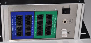
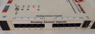
In the Vesta, discrete inputs and outputs are provided in groups of four. Standard Cat5 (Ethernet type) cables are used to connect discrete inputs and outputs to the Vesta.

The processes for connecting and configuring discrete inputs and discrete outputs are quite similar. In both cases, it's important to remember that each connector on the Vesta carries a block of four discrete channels so that the first connector is channels 1-4, the second is 5-8 and so on.

Discrete Inputs

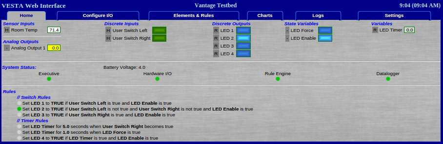
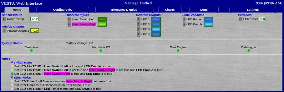
In the Vesta color scheme, discrete inputs are green. The discrete input section of web pages will be green, the legend on the discrete input section of the Vesta itself is green, and green cables are suggested for making connections.

Depending on the model, the Vesta provides either 16 or 32 channels of discrete inputs. These inputs are intended to be connected to dry contacts - that is, electrical contacts which do not have any voltage or power source connected to them. Examples would be switches, microswitches, some thermostat contacts, snap-action thermal switches, and magnetic door and window switches (as used on alarm systems). Another common use of discrete inputs is to monitor relay contacts in RI-024A and RI-110A sense relay boxes. There's an application note that covers an example of this.

Connecting Discrete Inputs

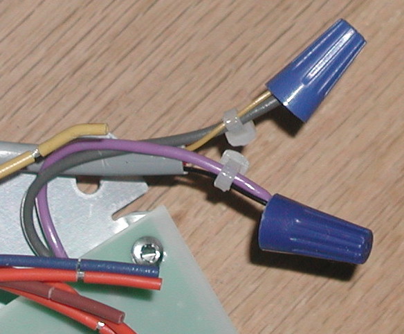
The Vesta uses discrete inputs to detect ‘dry contact’ closures. A Dry Contact is a mechanical switch or contact pair with no voltage present. If you're not sure whether a set of contacts qualifies as 'dry contacts', check with a handheld Voltmeter (in both AC and DC settings) when the switch is in both positions. There should be no voltage between the two contacts under any condition.

WARNING: The Vesta can be seriously damaged or destroyed if voltage is applied to a discrete input.

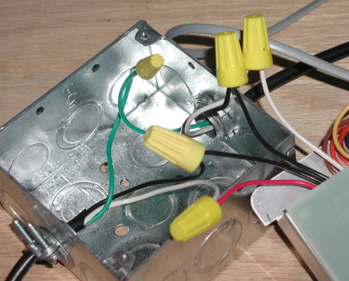
Discrete input connections are typically made using the DB-1195-IN box. Each DB-1195-IN provides a set of four independent inputs. The DB-1195-IN is connected to the Vesta using a standard CAT5 cable.

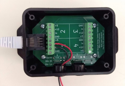
There are currently three different versions of the DB-1195-IN box, shown below. The oldest is at left, and the current version is at the right. In all cases, dry contact connections are made to the terminal strip. Each contact uses a numbered terminal and a ground terminal. In the left example below, connection has been made to input channel number 1.

Discrete Input Boxes

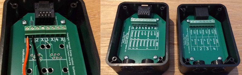
Figure 12.1: Discrete Input Boxes

Configuring Discrete Inputs

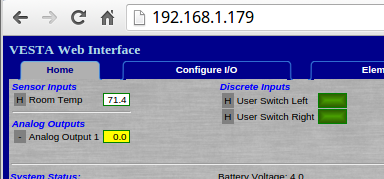
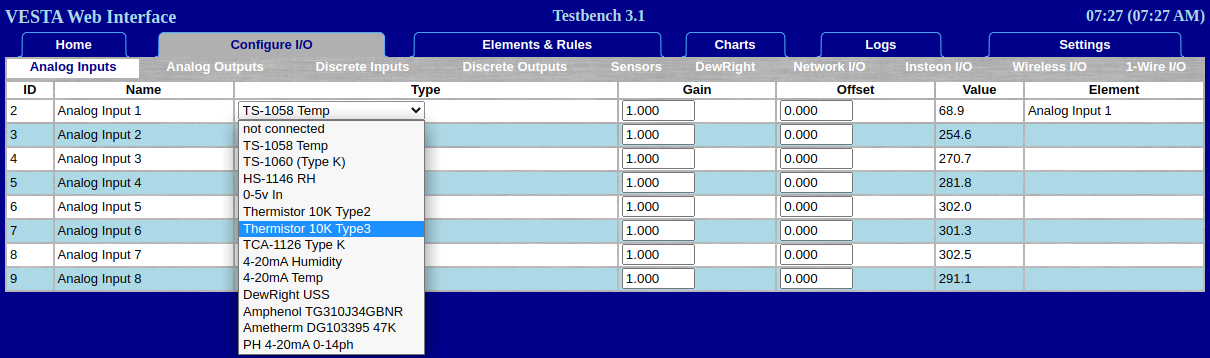
To configure discrete inputs, select the 'Discrete Inputs' sub-tab on the 'Configure I/O' tab. When configuring discrete input channels, the only option is whether or not to invert the sense of the electrical signal. A normal signal is TRUE when active and FALSE when inactive. An inverted channel has the opposite behavior.

A screenshot of Discrete Input configuration in the Configure I/O tab

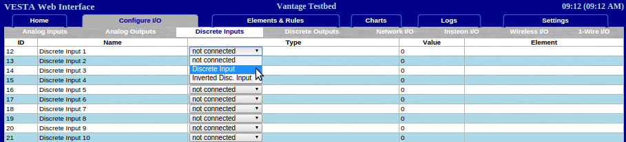
Figure 12.2: Discrete Input Configuration

Discrete Outputs

In the Vesta color scheme, discrete outputs are blue. The discrete output section of web pages are blue, the legend on the discrete output section of the Vesta itself is blue, and blue cables are suggested for making connections.

As with discrete inputs, the Vesta provides either 16 or 32 channels of discrete outputs depending on the model, grouped into sets of four, and connected using standard Cat5 
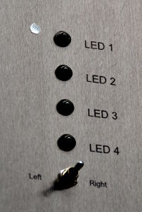
cable. The Vesta discrete outputs provide 12 Vdc at up to 200ma, suitable for driving most 12vdc relays as well as small buzzers and LEDs.

Connecting Discrete Outputs

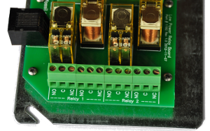
The Vesta uses discrete outputs to control devices that are either 'ON' or 'OFF'. In most cases, a Vesta discrete ouput port is connected to a relay box - the RC-4DD, RC-4SD-MINI, or other specialized models. The Vesta drives the relay coils, which then control signals or electrical power to pump, blowers, valves, lights, or other devices.

Discrete outputs can also be connected using the DB-1195-OUT breakout box. This is identical the the DB-1195-IN described above, except that each channel has a channel number terminal and a +12V terminal. Take care that there is never a direct connection between the two terminals.

WARNING: The Vesta can be seriously damaged or destroyed if discrete output terminals are shorted together.

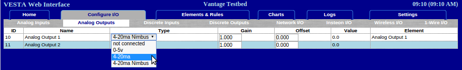
Configuring Discrete Outputs

The process for configuring discrete outputs is identical to discrete inputs described above, except that there's also a 'PWM' option.

The 'Discrete Output' and 'Inverted Disc. Output' behave just as for discrete inputs. PWM, or 'Pulse Width Modulation' is a special case. PWM outputs are 'on' for a percentage of the time. In the Vesta, each PWM output has a defined period in seconds and a control variable that determines the percentage of 'on' time in each period.

A screenshot of PWM Discrete Output configuration in the Configure I/O tab

Figure 12.3: Discrete PWM Output Configuration

When you designate a discrete output as PWM, you specify the length of the period, and there's an additional control variable that's created. It's initially named 'PWM Control XX', and it will appear in the 'Analog Output' section of the Vesta I/O. The value of that variable determines the percentage of each period that the output will be on. For example, if you specify a 40 second period and the control variable has a value of 25 (percent), then the output will be on for 10 seconds out of every 40.

The timing resolution of the PWM function is limited by how often the hardware I/O task runs. This is typically once or twice per second, so the resolution of periods and on / off portions of each period are in the range of +/- one second. PWM periods in the Vesta environment are typically 30 seconds or longer. A typical example of a PWM application might be a radiant heating zone where a circulator provides hot water. Radiant heat zones respond slowly. Rather than using a thermostat which would typically result in a one or two degree temperature fluctuation, a PWM output could control the circualtor, with a period of perhaps 5 minutes (300 seconds). A PID loop could then continually adjust the control variable to determine how long the circulator runs in each five minute period.

PWM Discrete Output Data Elements

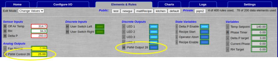
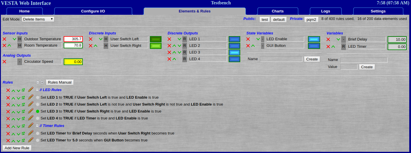
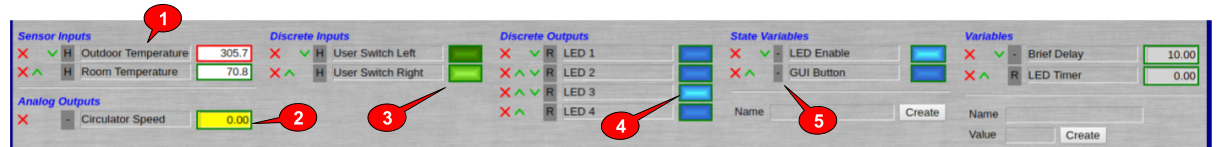
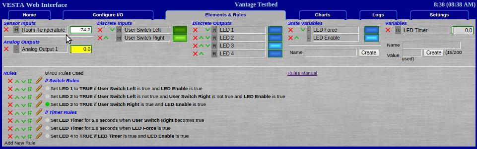
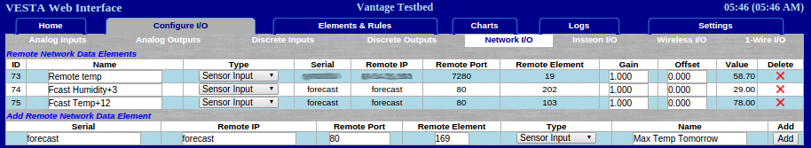
Figure 12.4: Discrete PWM Output Data Elements

The screenshot above shows a PWM output and the associated control variable. As with all data elements, these can be renamed as desired.

User Manual - Vesta Vantage or Pro | Vermont Energy Control Systems

Vermont Energy Control Systems

Practical monitoring and control for the real world

Relays

Relay Basics

Relays are key components of most electrical control systems, and the Vesta controller is designed to operate up to 32 relays.

While detailed relay theory is beyond the scope of this manual, there is a tutorial document on this site, and there are many online explanations such as this one.

Relays are typically used for two purposes:

  1. Control - To allow the Vesta controller to control some external device such as a valve or a circulator
  2. Sense - To allow the Vesta controller to sense the presence of electrical power that's provided by some other means, such as another controller. For instance, a relay could be used to detect that an oil boiler was running.

Control relays have 12Vdc coils and are directly controlled by the Vesta controller. Each control relay is driven by a discrete output.

Sense relays have coils that match the voltage that needs to be sensed. For instance, a relay that's used to sense whether a 120VAC pump is running would use a 120VAC coil wired in parallel with the pump motor. The relay contacts would in turn be connected to a Vesta discrete input. An example is described in this application note.

Control Relays

The Vesta controller discrete outputs can drive any relay that has a DC coil that operates at 12 Volts and draws less than 200ma of coil current. This includes virtually all 12Vdc relays.

External Relay Enclosure (RC-4DD)

A picture of the RM-1207 External Relay Enclosure

It is desirable to keep high voltages outside of the Vesta controller enclosure for three reasons:

  1. To avoid accidentally vaporizing expensive circuit boards
  2. To keep the Vesta controller enclosure intrinsically safe and finger-friendly
  3. To reduce the distance that power has to travel to get to the high voltage loads

To achieve these goals, the Vesta approach to controlling high voltage loads is to use a relay enclosure that is mounted near the loads and controlled by the Vesta controller. This relay enclosure can contain either control or sense relays. The most common use of external relays is typically control. The standard RC-4DD external relay enclosure is set up with four control relays. Note: The RD-4DD was formerly designated as the RM-1207.

Since each discrete output connector on the Vesta controller carries four channels, the capacity of an external relay box is four relays.

The RC-4DD Relay Module has an RJ45 connector for connecting to Vesta discrete outputs. Internally, each relay has two electrically separate sets of contacts, each with common (C), Normally Open (NO), and Normally Closed (NC) contacts. These are brought out to screw terminals for easy connection to electrical devices.

Wiring

A picture of the internal workings of a control relay

The RC-4DD is connected to any Discrete Output connector on the Vesta Controller using standard Cat5 Ethernet cable. The Vesta color code for discrete outputs is blue, so a blue cable is suggested.

The screw terminals in the relay module can accommodate up to 12 gauge stranded and 14 gauge solid wire if necessary, but smaller gauges are much easier to accommodate in the limited internal space.

As with all high voltage wiring, ensure that all relevant codes are followed.

WARNING: To avoid damage to the Vesta controller, disconnect the Vesta controller cable from the relay box before doing any wiring.

Sample External Control Relay Application

There is an application note that describes controlling a high voltage device with a Vesta discrete output using a relay.

User Manual - Vesta Vantage or Pro | Vermont Energy Control Systems

Vermont Energy Control Systems

Practical monitoring and control for the real world

Network I/O

The title 'Network I/O' is actually misleading. For security reasons, network communication with other Vesta systems is read-only: you can read values from another Vesta, but you cannot set values on another Vesta.

Configuration of network inputs is done on the 'Network I/O' sub-tab of the 'Configure I/O' tab.

Any configured data elements are in the top section, while the bottom section allows you to add networked data elements from remote systems.

The Vesta has no way to know what type of data element the remote system is supplying, so element type must be configured on this tab. This tells the Vesta where and how to display the data from the remote system.

You can name remote data elements here or on the 'Elements & Rules' tab. If you no longer need a remote data element, the red X in the top section will delete it from your system.

A screenshot of the user configuring Network I/O

Figure 15.1: Network I/O

To add remote data elements, you'll need the serial number of the remote Vesta as well as the Element ID for the data element that you want to read. If you know the IP address and/or data port number for the remote Vesta you can enter those as well.

Otherwise, the Vesta will obtain the most recently reported values from our registry. Choose an element type do determine how and where the data will be displayed. Note that remote data elements can only be inputs or variables.

User Manual - Vesta Vantage or Pro | Vermont Energy Control Systems

Vermont Energy Control Systems

Practical monitoring and control for the real world

Forecast Data

If the Vesta is connected to the Internet and is in the United States, it can obtain NOAA (National Oceanic and Atmospheric Administration) forecast data. This data is available in three hour increments for 48 hours into the future, and it's updated hourly. In addition to the raw NOAA data, the Vesta can also provide averaged values for various intervals as well as calculated insolation (solar energy).

Forecast data is a special class of Network I/O. To obtain forecast data, create remote data elements as described on the previous page, but with a serial number and remote IP of 'forecast'. The remote port is 80, and the remote element is chosen from the table at the end of this page to specify the desired forecast data. In the example below, forecast data is being obtained for humidity 3 hours in the future and temperature 12 hours in the future. A new data element is being created that will obtain the maximum temperature for tomorrow (remote element 169).

A screenshot of forecast elements added to the Network I/O tab

Figure 15.2: Forecast Data Elements in Network I/O Tab

Available Data

The following data is available:

  • Temperature in degrees Fahrenheit
  • Relative Humidity in percent
  • Wind Speed in miles per hour
  • Cloud Cover in percent
  • Insolation (described below)

Each of these parameters is available for every three hour period in the next 48 hours. Average or total values are also available for selected intervals.

Insolation

It's often useful to know how much sunlight to expect. Insolation is a sunlight intensity forecast for each three hour period of the day based on cloud cover and the sun's average altitude during that period. Sun altitude is calculated from time of day, day of the year, and latitude. Sun altitude (and resulting insolation) is higher in the middle of the day than in the morning or evening, and higher in summer than winter.

A single insolation value can't precisely predict the effect of sunlight in any specific situation. Sunlight may be of interest for solar PV panels, solar hot water panels, crops, greenhouses, building heat loads, and many other purposes. Each application responds differently to sunlight at different angles or with differing amounts of cloud cover. For this reason, insolation values enable comparing one period to another, but they do not provide a basis for numeric performance prediction.

Insolation is calculated by taking expected intensity based on sun angle and reducing that value based on cloud cover. For example, if the sun angle would be expected to provide 20 units of insolation, a cloud cover of 10% would result in 18 units. An implication of this is that 100% cloud cover results in an insolation value of 0.

Units for insolation are roughly the percentage of maximum possible daily total for the summer solstice at 44 degrees North latitude. This is an arbitrary value, of course, but it provides a reasonable basis for comparing sunlight intensity from one period to another. It doesn't make sense to average insolation values, so they're instead available as totals for the selected period.

Here's sample insolation values for each three hour period for a clear day near 44 degrees North Latitude on the summer solstice. Note that the 11:00 to 14:00 period contributes more than 30 units out of a total of 98 for the day.

Start Time Insolation
2:00 0.0
5:00 7.0
8:00 22.9
11:00 30.7
14:00 25.9
17:00 11.3
20:00 0.0
23:00 0.0

Here's the same table for the winter solstice. Note the shorter day and the effect of the lower sun angles. The total for the day is less than a quarter of the amount on the summer solstice.

Start Time Insolation
2:00 0.0
5:00 0.0
8:00 8.5
11:00 12.2
14:00 3.3
17:00 0.0
20:00 0.0
23:00 0.0

Time Periods

The raw NOAA data contains average values for each three hour interval in the next 48 hours. The first available interval starts between 0 and 3 hours from the present. You can request data for any future period within the 48 hour window.

Current NOAA practice is that the starting hour for the data set will always be one of 02:00, 05:00, 08:00, 11:00, 14:00, 17:00, 20:00, or 23:00.

The Vesta can also obtain averages for other periods (or in the case of insolation, sums for selected periods). In addition to the three hour blocks, there are several other available time periods:

Six Hour Blocks

In this case, the Vesta will provide average values for each six hour block starting with the first available data. You may specify the first or any subsequent six hour block. Note that these blocks will not start at the same time of day. Instead, they start with the first available data. Each subsequent block starts six hours later.

12 and 24 Hour Blocks

These follow the same format as the six hour blocks.

Rest of Today/Tomorrow (midnight)

Unlike the 6/12/24 hour blocks, this interval is based on time of day. Because the NOAA data does not align with midnight, days for this purpose start and end at 23:00 (11:00 PM). Thus, 'today' means every 3 hour period between the current time up to (but not including) the period starting at 23:00. 'Tomorrow' means the period between the 23:00 tonight up to (but not including) the period starting at 23:00 tomorrow night.

For example, if it's 9:00 AM on January 11, here's what you would get for 'rest of today' and 'tomorrow'.

Rest of Today - Average (or sum) of the following periods:

Date Start Time
January 11 11:00
January 11 14:00
January 11 17:00
January 11 20:00

Tomorrow - Average(or sum) of the following periods:

Date Start Time
January 11 23:00
January 12 02:00
January 12 05:00
January 12 08:00
January 12 11:00
January 12 14:00
January 12 17:00
January 12 20:00

Rest of Today/Tonight (day/night)

As with the previous example, these intervals are based on time of day. In this case, the day is divided into day and night periods. Due to the structure of the NOAA data, the day/night boundaries are 8:00 AM and 8:00 PM. The first choice in this section will give you each 3 hour period from the current time up to (but not including) 8:00 AM or PM. Each subsequent interval is the next 12 hour day or night.

Element IDs for Forecast Data

The table below shows the element IDs that correspond to different forecast data. To use this table, find the column for the type of data you want (Maximum Temperature or Average Cloud Cover, for instance). Then find the row for the time period you want. The element ID in the selected row and column will provide the data that you want.

For example, maximum temperature for tomorrow would be element 169.

A chart of element IDs corresponding to forecast data

Figure 15.3: Forecast Data Element Table

User Manual - Vesta Vantage or Pro | Vermont Energy Control Systems User Manual - Vesta Vantage or Pro | Vermont Energy Control Systems

Vermont Energy Control Systems

Practical monitoring and control for the real world

Wireless Sensors

The Vesta Vantage and Pro models support a wide range of wireless sensors. These sensors will be detected by the Vesta if they are powered on and within range. The Wireless I/O tab allows you to add, remove, and configure wireless sensors as well as monitoring signal strength and battery levels.

A screenshot of wireless I/O in the Configue I/O tab

Figure 17.1: Wireless I/O

This page has three sections. The top section lists wireless devices that are being managed by the Vesta. For these sensors you can see battery level and signal strength. Depending on the battery type, above 2.8 volts and -95dBm is good. (Note: -63dBm is above -95dBm - these are negative numbers.) It's important to note that in multi-Vesta installations there may be wireless sensors that can be detected by more than one Vesta, but each sensor can be registered to (and managed by) a single Vesta controller.

The second section lists wireless sensors that have been detected by the Vesta but are not currently registered. In both of the two first sections, the red X will cause the Vesta to delete all record of the associated sensor. This might be appropriate if a sensor is lost or destroyed, for instance.

The third section lists the data elements associated with wireless sensors. There's a bit of added complexity here, since some wireless sensors provide more than one data element. The 'Add' and 'Unlink' buttons perform slightly different actions depending on the sensor. If the sensor is a multivalue type, it's possible that you may only care about a subset of the data elements associated with that sensor. For instance, if it's a temperature and humidity sensor you might only care about the humidity. By default, all data elements are hidden until the user selects them.

If the sensor is a simple single-value type, 'Add' equates to 'Register'. The sensor will now be managed by the Vesta, and the associated data element will be visible to be logged, renamed, and/or used in rules. The 'Unlink' button equates to 'Unregister'. The sensor is forgotten and all record of it is deleted.

If the sensor is a multivalue type, the 'Add' button will register the sensor and make the data element on the 'Add' line visible to the system. However, any additional data elements for that sensor will still be hidden. Clicking 'Add' on any of the additional data element lines will make the associated elements visible. In the same way, 'Unlink' will only hide data elements unless 'Unlink' is clicked for the last visible data element - in that case, the sensor will also be unregistered.

User Manual - Vesta Vantage or Pro | Vermont Energy Control Systems

Vermont Energy Control Systems

Practical monitoring and control for the real world

1-Wire Devices

1-wire sensors allow many (typically up to ten) sensors to be connected to a single port. Each sensor has a unique ID. The Vesta can detect 1-wire sensors that have been connected, and the 1-Wire I/O tab allows configuration of these sensors.

Screenshot of 1-Wire I/O in Configure I/O tab

Figure 18.1: 1 Wire I/O

The logic and operation of this page is exactly the same as for the wireless sensors in the previous page. There are three sections. 1-wire devices can be registered or unregistered, and 1-wire devices can have more than one data element associated with them. In that case, each individual data element can be visible or hidden.

User Manual - Vesta Vantage or Pro | Vermont Energy Control Systems

Vermont Energy Control Systems

Practical monitoring and control for the real world

Analog Output

Analog outputs are most commonly used for variable speed control, but they can be connected to anything that can be controlled by a 0-5V or 4-20mA signal. If needed, a 0-10V output is also easily achieved. Contact VECS for more information on this option.

When connecting an analog output, there are four choices:

  • 0-5V. In this case, output values of 0 to 5 correspond to equivalent voltages at the output connector.
  • 4-20mA. In this setting, an output value of 0 corresponds to 4mA, and an output value of 100 corresponds to 20mA.
  • 4-20mA Nimbus. In this setting, 0 corresponds to a zero output from the Nimbus controller usid in the VS-1108 variable speed controller, and 100 corresponds to full output.
  • 0-100%. This is similar to the 4-20mA Nimbus, but 0 is zero output and 100 is full output.

Choose an output type appropriate for your application. When using the VS-1108, choose the '4-20mA Nimbus' setting.

A screenshot of configuring the Analog Outputs

Figure 6.2: Analog Outputs

Connecting Third-party Devices

In order to connect a third-party device (such as a motor VFD or a modulating valve) the individual pins on the Vesta connector are made available on a terminal strip using the RJ12-INT interface box.

NOTE: The Vesta analog outputs are not electrically isolated from each other - they share a common ground. This means that in some situations with more than one analog output channel in use in current loop mode, the devices being contrrolled may need to be electrically isolated from the Vesta. This can be accomplished using readily available isolation modules. Contact VECS if you are planning to use the Vesta to control more than one 4020mA device.

VS-1108 Variable Speed Control

The VS-1108 Variable Speed Control Unit provides variable speeed control of devices that are normally fixed-speed. These devices include small circulators, fans, and heaters powered by 110VAC to 220VAC and up to 2.0A. Not all devices are compatible. Contact VECS to verify your intended application.

The VS-1108 is typically mounted next to the device that's being controlled in order to keep high voltage wire lengths to a minimum. There is a light gauge cable connecting the Variable Speed Control unit to the Variable Speed Breakout Box that's typically mounted next to the Vesta controller. This cable uses a standard RJ11 connector on the Vesta controller end and is hard-wired to the control unit. The example photos here are for a benchtop demo and use standard appliance line cord for the high voltage (115Vac) wiring. Actual installations would typically use armored BX cable or a code-compliant equivalent.

Configuring the Control Unit

DIP Switches

A picture of the dip switches in the Nimbus

The heart of the Control Unit is the 'Nimbus' manufactured by Control Resources. In the Vesta controller application, it's configured to be controlled by a 4-20ma signal. The DIP switches should be set according to the picture at the right - switches 1, 2 and 7 on and the rest off.

Jumper

A picture of the jumper in the Nimbus

There's also a jumper which needs to be installed on the two pins nearest the edge of the card. This photo is courtesy of Smokeless Heat in Pennsylvania. They use the Vesta controller with an interesting Swedish boiler, and have quite a bit of experience with the Nimbus variable speed controller.

The Nimbus is a quite sophisticated device. There is a complete manual available from Control Resources.

Connecting Power and Load

A picture of the wiring connecting power and load

The Control Unit requires connection to both 115vac and the load that is to be controlled. These connections are made as shown in the photo below, The load is to the left and is connected to the red and black wires at the left end of the row of wires (when viewed as shown). The next two wires (black and white) are connected to 115vac power.

Connecting the Control Signal

A picture of the wiring connecting the control signal

The last connection that's required is the control signal from the Variable Speed Breakout Box. This signal will be provided via an RJ11 cable (typically flat 4 conductor). If the standard 4 conductor color code is used, the signal is on black and yellow, corresponding to pins 1 and 4. If six conductor cable is used, the control is on pins 2 and 5.

The black wire (pin 1) is connected to the purple wire on the control unit, and the yellow wire (pin 4) is connected to the gray wire. Because the signal wires are so small, use cable ties to tie the signal wires to the control unit wires as shown.