
Discrete Inputs
The processes for configuring discrete inputs and discrete outputs are quite similar. In each case, it's important to remember that each connector on the Vesta carries a block of four discrete channels so that the first connector is channels 1-4, the second is 5-8 and so on.
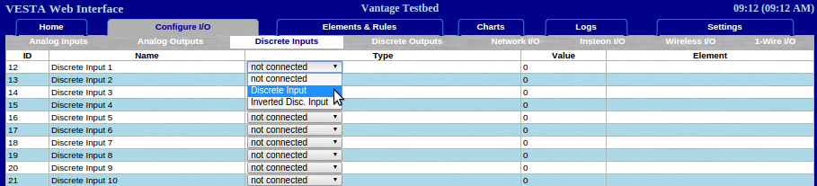
Figure 12.1: Discrete Input Configuration
When configuring discrete channels, the only option is whether or not to invert the sense of the electrical signal. A normal signal is TRUE when active and FALSE when inactive. An inverted channel has the opposite behavior. Inverted I/O is for special cases only.
The Vesta provides either 16 or 32 channels of discrete inputs. These inputs are intended to be connected to dry contacts - that is, electrical contacts which do not have any voltage or power source connected to them. Examples would be switches, microswitches, some thermostat contacts, snap-action thermal switches, and magnetic door and window switches (as used on alarm systems).
If you're not sure whether a set of contacts qualifies as 'dry contacts', check with a handheld Voltmeter (in both AC and DC settings) when the switch is in both positions. There should be no voltage between the two contacts under any condition.
In the Vesta, discrete inputs are provided in groups of four. Standard Cat5 (Ethernet type) cables are used to connect discrete inputs to the Vesta. A common use of discrete inputs is to monitor relay contacts in RI-024A and RI-110A sense relay boxes. There's an application note that covers an example of this.