
Elements & Rules Tab
This is the primary working tab for working with the Vesta, and is password protected. This tab is similar in layout and appearance to the 'Home' tab, and like the Home tab it provides continuous live update of element and rule status and values. However, this tab provides additional capabilities:
- The ability to rename data elements
- Creation and deletion of rules and variables
- Reordering of data elements and rules
- Setting values for variables and outputs
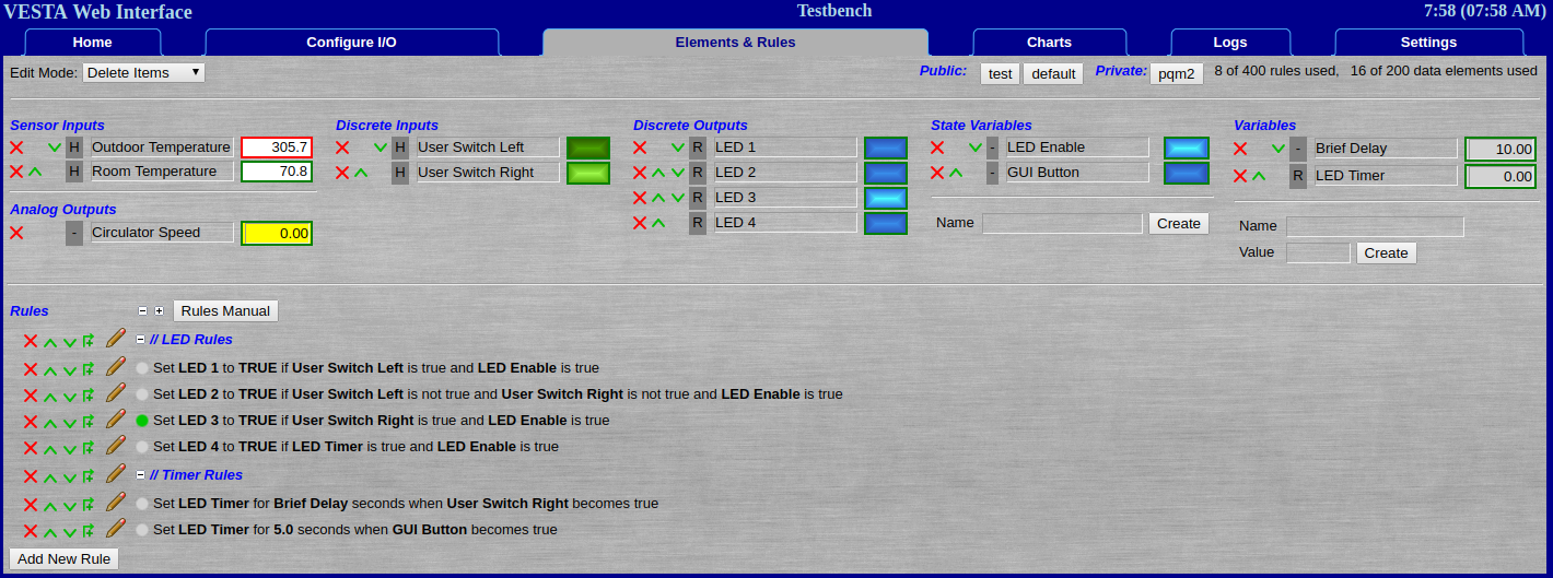
Figure 7.1: Elements & Rules Tab
This screenshot shows the sample rule set that's configured on new Vesta systems by default. Even in this simple example, there's quite a bit going on. This is a complex page, and it's important to understand each section. We'll go through this page in detail, starting at the top.
Edit Mode, Custom GUI, and Resource Usage
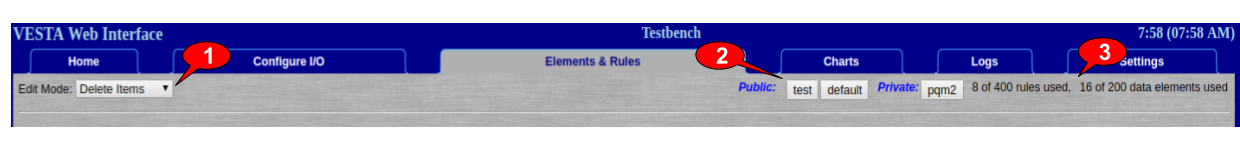
Figure 7.2: Edit Mode, Custom GUI, and Resource Usage
- The user has chosen an edit mode of 'Delete Items'.
- There are a few 'Custom GUI' pages available.
- We've used relatively few of the available rules and data elements.
1: Edit Modes
In newer Vesta models (software version 3.1.1590 and newer) the Elements & Rules tab has multiple edit modes. These are primarily intended to reduce the chance of making accidental changes - especially deletions. There are four edit modes:
- Change Values: The values of outputs and variables can be changed. Rules can be edited.
- Move Items: Same as 'Change Values', but the order of elements and rules can be changed. New elements and rules can be created.
- Delete Items: Same as above, except elements and rules can be deleted. Use with caution.
- Simulate: This is a special mode for testing rules. To use this mode, first go to the 'Settings' tab turn off any hardware I/O processes. In 'Simulate' mode the user can set the values of sensors and discrete inputs.
2: Custom GUI Pages
The Vesta provides the ability to create custom Graphical User Interface (GUI) pages. The buttons in this part of the page provide access to any existing custom GUI pages. Custom GUI pages can be configured to be accessed without a password (Public) or password protected (Private). There's a separate manual here that covers the custom GUI feature in detail. In this example there's the blank 'default' GUI that's distributed with the Vesta as well as a two created by the user - a public GUI named 'test' and a private GUI named 'pqm2'.
3: Resource Usage
The Vesta has some limits on the number of data elements and rules allowed. These limits may vary by model and application, but this section of the the Elements & Rules tab shows both current usage and the Vesta's limits.
Data Elements: Values, Status, and Editing
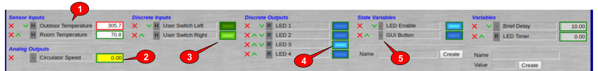
Figure 7.3: Data Elements: Values, Status, and Editing
This section of the page deals with Data Elements. In the image above, there are several things going on:
- There are two sensor inputs. The one named 'Outdoor Temp' has a red border around the value which tells us that it's currently invalid. In this case, the Vesta has detected that the sensor is not connected.
- There's an analog output named 'Circulator Speed' with a value of 0.0. The '-' to the left tells us that there isn't any process setting its value.
- The illuminated green rectangle next to the discrete input 'User Switch Right' tells us that the user-definable switch on the front cover is in the rightmost position.
- The illuminated blue rectangle next to discrete output 'LED 3' tells us that front panel LED 3 is on. Of course, if we're within sight of the Vesta, we probably know that anyway.
- No process is setting the values of the two state variables, so they can be set by the user - simply clicking on the blue rectangles will toggle them.
This section provides complete control over data elements - the user may create, delete, reorder, and change values. The only exceptions are that data elements dor physical I/O are created on the 'Configure I/O' tab, and the user can't set values for data elemements that are managed by the Vesta. For instance, the user can't set Outdoor Temperature.
On this page, variables and state variables can be created using the 'Create' forms in each section.
Any data element can be renamed by simply typing a new name.
Elements and rules can be deleted by clicking the red X next to them, and they can be reordered by clicking the green up or down arrows.
As long as no Vesta process is managing them, discrete outputs and state variables may be toggled between 'True' and 'False' by clicking the blue rectangle next to them.
As long as no Vesta process is managing them, the values of analog outputs and variables may be set by typing in new values. For instance, the user could change the value of 'Brief Delay' or set the Circulator Speed by typing in new values.
All instances of a data element can be highlighted by hovering over any instance of the element name. The highlight can be locked and unlocked by clicking on any instance of an element name. This is useful to see what rules reference a particular data element.
Rules: Status and Editing
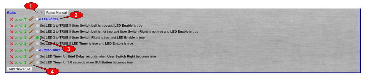
Figure 7.4: Rule Status and Editing
This section of the page deals with rules. There's a separate manual that describes rules in detail.
Editing
(1) The small '+' and '-' icons expand and collapse section of the rules. The 'Rules Manual' button opens a separate window (or tab) with the rules manual.
(2) There's a special rule type called 'Comment'. It does nothing except to help document rules and serve as a divider between different groups of rules.
(4) Depending on the edit mode chosen, there are several icons at the left of each rule. As with data element, the 'X' and up / down arrow icons allow rules to be deleted or rearranged. The next icon is an 'up-over and plus' icon, and it adds a rule just above the existing rule. The pencil icon allows a rule to be edited.
Status
(3) Next to each rule, there's a colored status dot. It's green if the rule is currently triggered. In this example, we can see that there's one rule that's triggered. Looking at the rule, we can see that LED 3 is set to TRUE (on) because 'User Switch Right' is true and 'LED Enable' is true. Looking pack at the top of this page, we can see that LED 3 is in fact on, as are User Switch Right and LED Enable.
Finally, the 'Add New Rule' button adds a new rule at the bottom of the list of rules.