
Home Tab
The home page displays current values for all configured inputs and outputs. It also displays the system rules and the status of the system software processes. The home page does not require a password, since it provides only a passive view of system data. On your local network, it will automatically update values and rule status.
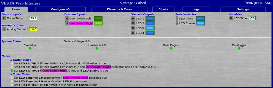
Figure 5.1: Home Tab
Top Section
The top portion of this page shows the current value for each input, output, and variable in the system, collectively referred to as 'data elements' in this document.
There's a letter next each data element that identifies the system task that's responsible for providing the values that you see. These letters match the first letter of the task names in the status section below. For example, task R is the rule engine and H is the Hardware I/O task. Any data element with a '-' next to it gets its value from the user - there's no system task that will provide a value.
This is covered in more detail in the programming guide.
There's a colored border around each data element value. This color indicates the status of that value:
- Green: The value is valid and up to date as far as the controller can determine.
- Yellow: The value has not been updated as recently as expected, but is not seriously out of date.
- Red: The value is suspect - out of range or out of date.
- Black: The controller cannot tell whether the value is valid or not. This can happen with sensors that report only when an event happens, such as Insteon door sensors.
System Status
This section shows status of all the software processes that are supposed to be running on the system. Green is good, yellow indicates a (potentially) temporary problem, and red indicates a failure. Selection of the processes that are intended to be running is accomplished on the 'Settings' tab.
Rules
This section lists all the rules that have been defined. Any active rule will have a green dot next to it. This can help quickly show what's happening with the system. In this example, the rule setting LED 3 is active. LED 3 is 'TRUE' (on) because 'User Switch Right' is true and 'LED Enable' is true.
To aid in understanding what's going on in a more complex configuration, hovering the mouse over the name of any data element will highlight all the places where that data element is defined or used. In this case, we can see that 'User Switch Right' is defined as a discrete input (that's currently TRUE - see the indicator next to it in the top section). 'User Switch Right' is also used in three rules.