All I/O is via standard RJ-45 Ethernet connectors and RJ-12 telephone connectors. These cables, connectors, and related tools are inexpensive, reliable, and widely available.
While the Vesta uses these connectors and cables, the signals are not Ethernet or telephone. Vesta cables should never be plugged into Ethernet and telephone equipment (and vice versa). The only exception is the Vesta Ethernet connection itself.
RJ-11 / RJ-12 Cables
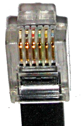
Telephone cables have at least two different color codes, and they may have either 4 or 6 conductors. All telephone cable plugs and jacks have 6 connector positions. If all 6 are used, it's referred to as an RJ-12 connector. If only the middle 4 are used, it's an RJ-11. With the connector tab facing away from you and cable hanging downwards, pins are numbered starting at the left:

In this image, you can just make out the colors of the individual conductors.
Warning: Do NOT use pre-made telephone cables with the Vesta. These cables have the conductors reversed on one end, and may cause damage to the Vesta hardware.
All current production sensors only use the four middle conductors. They are shipped with 4 conductor flat cable and RJ-11 connectors.
RJ-11 / RJ-12 pinout
| RJ-12 Pin | Color Code 1 | Sensor Input (Classic) | Sensor Input (Early Vantage) | Sensor Input(Current Vantage & Pro) | Analog Output | Modbus | RS-232 | 1-Wire | Color Code 2 | RJ-11 Pin |
|---|---|---|---|---|---|---|---|---|---|---|
| 1 |  | +5 V | Input - | Input - | +5 V | Ground | CTS | +5 V | ||
| 2 |  | Ground | Ground | Ground | 4-20mA- | RXD+ | RXD | Ground |  | 1 |
| 3 |  | Input | Input | Input (V or 4-20mA+) | Ground | RXD- | GND | Data |  | 2 |
| 4 |  | +12 V | +12 V | +12 V | Output | TXD- | GND | Return |  | 3 |
| 5 |  | +5 V | +5 V | +5 V | 4-20mA+ | TXD+ | TXD |  | 4 | |
| 6 |  | Input | 4-20mA+ | Thermistor Ground | +12 V | Ground | RTS | +12 V |  |
RJ-45 Cables and Connectors
RJ-45 cables are used for all discrete I/O, and they're used with sensor breakout boxes.
There are two conventions for Ethernet conductor color codes - T-568A and T-568B. Any commercial Ethernet cable may be used as long as it's not a 'crossover' cable. If you make your own cable, it doesn't matter what color code you use as long as it's the same on both ends.
Warning: Test hand-made cables with a cable tester before use. An incorrectly wired cable can cause permanent damage to the Vesta.
Pinout
This section is primarily for reference only - there shouldn't be any reason to be working with individual conductors.
As much as possible, power and ground are on conductors that are unused in Ethernet applications to reduce the risk of damage if cables are inadvertently plugged into network equipment.
In the cases where there are multiple pins with the same signal, they are electrically interchangeable.
| Pin | T-568A Color | T-568B Color | Sensor Breakout | Digital Input | Digital Output |
|---|---|---|---|---|---|
| 1 |  |  | Channel 1 | Channel 1 | Channel 1 |
| 2 |  |  | Channel 2 | Channel 2 | Channel 2 |
| 3 |  |  | Channel 3 | Channel 3 | Channel 3 |
| 4 |  |  | Ground | Ground | +12 V |
| 5 |  |  | +5 V | Ground | +12 V |
| 6 |  |  | Channel 4 | Channel 4 | Channel 4 |
| 7 |  |  | +12 V | Ground | +12V |
| 8 |  |  | Ground | Ground | +12 V |
