Introduction
Relays are an essential component of almost any control system. They are most often used to allow a small low voltage signal to control a large high voltage load, but there are many other applications. This page will show some examples of different ways that relays are commonly used with the Vesta system.
Relay Operation and Terminology
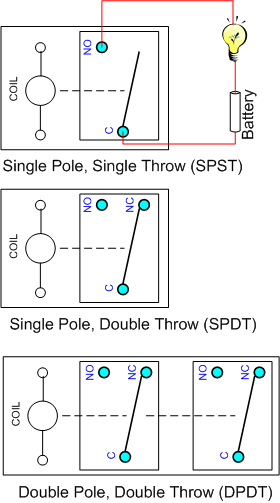
A relay is an electrically operated switch. A relay has a coil and one or more sets of contacts. When power is applied to the coil, the contact(s) change position. A relay with power applied to the coil is said to be energized. In the first example on the right, a circuit is wired with a battery, a light bulb, and a relay. If power is applied to the relay coil, the relay will move to connect the 'C' contact to the 'NO' contact. Current can then flow through the circuit and the light bulb will be illuminated.
Coil Voltage: The coil can be almost any voltage, and may operate on alternating current (AC) or direct current (DC). A standard Vesta relay module is the RC-4DD (formerly RM-1206) which has four relays with 12vdc coils. These relays are operated by discrete outputs on the Vesta controller. The Vesta controller can handle multiple relay modules.
Poles: In relays, a set of contacts is called a pole. A relay with one set of contacts is called a 'single pole relay', and a relay with two sets is called a 'double pole relay'. If there are two or more sets of contacts, they are electrically isolated from each other. The top two relays on the right both contain a single set of contacts and are therefore single pole relays.
Single vs. Double Throw: There are two basic configurations of contacts. The simplest is two contacts which are either connected or not connected. In relay terminology this configuration is referred to as single throw or 'Form A'. A more complex configuration is a common (C)contact which is connected to a second contact when the relay is not energized, or to a third contact when it is energized. This is referred to as double throw. A wall switch with this configuration is known as a three-way switch. The top relay on the right has contacts in a single-throw configuration, while the second one has double-throw contacts. Double-throw contacts are also sometimes referred to a 'Form C' contacts.
Contact Terminology: Each pole in a relay has two or three contacts. There's always a common (C) contact. A contact that is connected to the common when the relay is not energized is called normally closed (NC), while a contact that's not connected when the relay isn't energized is called normally open (NO). In schematics, relay contacts are drawn in the 'normal' (un-energized) position.
The drawings at the right show a variety of relay configurations. The relays in the RC-4DD have double pole, double throw (DPDT) contacts. All three contacts (common, normally open, and normally closed) for each pole are available on a screw terminal header inside the RC-4DD enclosure.

The drawing below shows a pair of DPDT relays. The one on the left shows the contacts in the non-energized position, while the one on the right shows the contacts in the energized position.

Contact Numbering
There are multiple standards that govern the numbering of relay contacts. This table lists the three most common for a DPDT relay:
| Function | Contact | US/Canada | DIN | EN-50005 |
|---|---|---|---|---|
| Coil | Terminal 1 | 1 | 85 (-) | A1 |
| Terminal 2 | 8 | 86 (+) | A2 | |
| Contact Set 1 | Common | 3 | 87 | 11 |
| Normally Open | 4 | 87b | 14 | |
| Normally Closed | 2 | 87a | 12 | |
| Contact Set 2 | Common | 6 | 88 | 21 |
| Normally Open | 5 | 88b | 24 | |
| Normally Closed | 7 | 88a | 22 |
The contacts in Vesta relay modules are labeled using standard C / NC/ NO lettering as well at the international (EN-50005) standard numbers.
Typical Applications
There are several common uses of relays. We have application notes that describe some different ways to use relays in the Vesta system.
Controlling a High Power Load
This is one of the most common uses of relays. High power loads include pumps, valves, lights, fans, blowers and other devices that require more power than the 200mA at 12VDC that the Vesta is capable of.
See the application note on controlling a circulator for an example of using relays to control a high power load.
Sensing High Voltage
Sometimes the Vesta controller needs to be able to determine whether a high voltage is present - perhaps to see if AC power is on, or to see if another controller has turned on a high power device.
See the application note on monitoring a pump for an example of using a relay to sense whether a high voltage device is powered on.
