Analog Output
Analog outputs are most commonly used for variable speed control, but they can be connected to anything that can be controlled by a 0-5V or 4-20mA signal. If needed, a 0-10V output is also easily achieved. Contact VECS for more information on this option.
When connecting an analog output, there are four choices:
- 0-5V. In this case, output values of 0 to 5 correspond to equivalent voltages at the output connector.
- 4-20mA. In this setting, an output value of 0 corresponds to 4mA, and an output value of 100 corresponds to 20mA.
- 4-20mA Nimbus. In this setting, 0 corresponds to a zero output from the Nimbus controller usid in the VS-1108 variable speed controller, and 100 corresponds to full output.
- 0-100%. This is similar to the 4-20mA Nimbus, but 0 is zero output and 100 is full output.
Choose an output type appropriate for your application. When using the VS-1108, choose the '4-20mA Nimbus' setting.

Figure 6.2: Analog Outputs
Connecting Third-party Devices
In order to connect a third-party device (such as a motor VFD or a modulating valve) the individual pins on the Vesta connector are made available on a terminal strip using the RJ12-INT interface box.
NOTE: The Vesta analog outputs are not electrically isolated from each other - they share a common ground. This means that in some situations with more than one analog output channel in use in current loop mode, the devices being contrrolled may need to be electrically isolated from the Vesta. This can be accomplished using readily available isolation modules. Contact VECS if you are planning to use the Vesta to control more than one 4020mA device.
VS-1108 Variable Speed Control
The VS-1108 Variable Speed Control Unit provides variable speeed control of devices that are normally fixed-speed. These devices include small circulators, fans, and heaters powered by 110VAC to 220VAC and up to 2.0A. Not all devices are compatible. Contact VECS to verify your intended application.
The VS-1108 is typically mounted next to the device that's being controlled in order to keep high voltage wire lengths to a minimum. There is a light gauge cable connecting the Variable Speed Control unit to the Variable Speed Breakout Box that's typically mounted next to the Vesta controller. This cable uses a standard RJ11 connector on the Vesta controller end and is hard-wired to the control unit. The example photos here are for a benchtop demo and use standard appliance line cord for the high voltage (115Vac) wiring. Actual installations would typically use armored BX cable or a code-compliant equivalent.
Configuring the Control Unit
DIP Switches

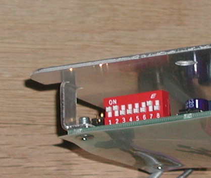
The heart of the Control Unit is the 'Nimbus' manufactured by Control Resources. In the Vesta controller application, it's configured to be controlled by a 4-20ma signal. The DIP switches should be set according to the picture at the right - switches 1, 2 and 7 on and the rest off.
Jumper

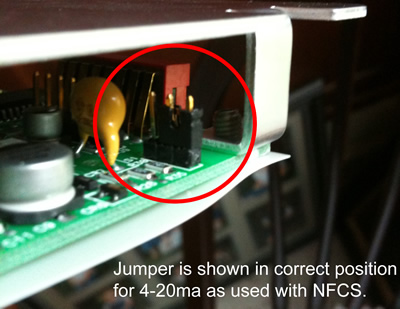
There's also a jumper which needs to be installed on the two pins nearest the edge of the card. This photo is courtesy of Smokeless Heat in Pennsylvania. They use the Vesta controller with an interesting Swedish boiler, and have quite a bit of experience with the Nimbus variable speed controller.
The Nimbus is a quite sophisticated device. There is a complete manual available from Control Resources.
Connecting Power and Load

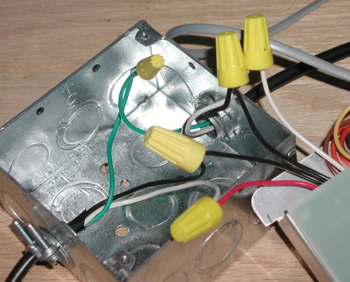
The Control Unit requires connection to both 115vac and the load that is to be controlled. These connections are made as shown in the photo below, The load is to the left and is connected to the red and black wires at the left end of the row of wires (when viewed as shown). The next two wires (black and white) are connected to 115vac power.
Connecting the Control Signal

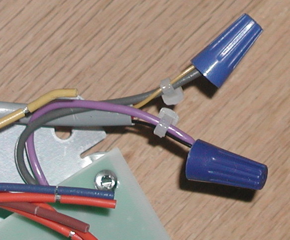
The last connection that's required is the control signal from the Variable Speed Breakout Box. This signal will be provided via an RJ11 cable (typically flat 4 conductor). If the standard 4 conductor color code is used, the signal is on black and yellow, corresponding to pins 1 and 4. If six conductor cable is used, the control is on pins 2 and 5.
The black wire (pin 1) is connected to the purple wire on the control unit, and the yellow wire (pin 4) is connected to the gray wire. Because the signal wires are so small, use cable ties to tie the signal wires to the control unit wires as shown.
